
QSFP112 PRODUCTS RELEASE UPDATE Sep.2021
Hangzhou, China, September 16, 2021
Since the official release of QSFP112 hardware specification Rev1.0 in June 2021, the industry has officially started the planning, design and implementation of the next-generation QSFP112 400G-related products. Some downstream large data center vendors were already planning and initiating hardware system solutions for next-generation QSFP112 400G-based networks, including design and consideration of single-chip-based box architectures and optical interconnect solutions. This drived upstream manufacturers to release related component products in advance, such as electrical connectors, DACs, optical modules, etc.
1.Components
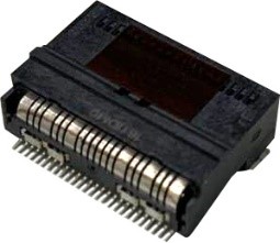
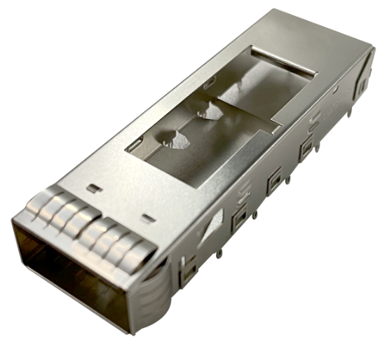
In July 2021, Luxshare-Tech officially announced that T0 sample testing of SMT type 1x1 connector and cage compliant with QSFP112 MSA specification was completed and this product achieved NPI status.
In July 2021, Luxshare-Tech officially announced T0 sample testing of QSFP112 400G DAC compliant with QSFP112 MSA specification was completed and this product achieved NPI status.
2.System-level prototypes
In July 2021, a 4U box prototype based on 112G-PAM4 serdes, jointly designed by Alibaba and Ruijie, was officially started testing. This prototype used current high-capacity switch ASIC based on 112G-PAM4 Serdes, and aimed to provide prior test and experimental data for high-speed interconnect solutions, thermal solutions and optical interconnect solutions for the next-generation 51.2T 128x400G (QSFP112) scenario. Therefore, this prototype was intentionally designed with different types of high-speed link models including various active and passive electrical channels, such as the passive channel on single PCB from ASIC to QSFP112 IO directly, the passive channel across board-to-board connector, the passive channel across Qpath (cabled chip to IO), and active channel across OD connector via re-timers of different vendors.

2.1 DAC loopback BER test of passive channel (ASIC to IO)
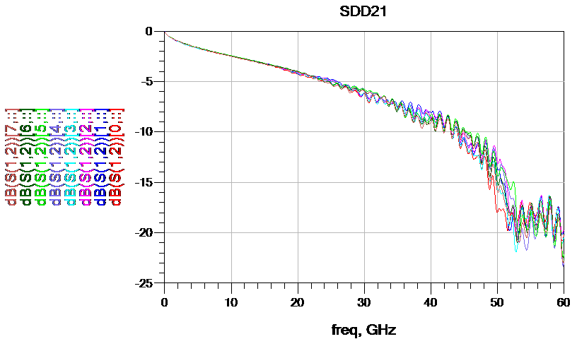
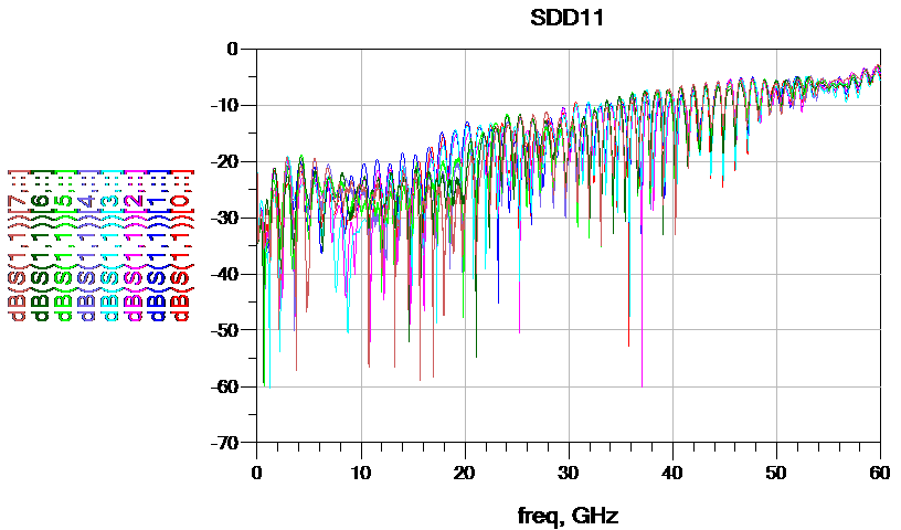
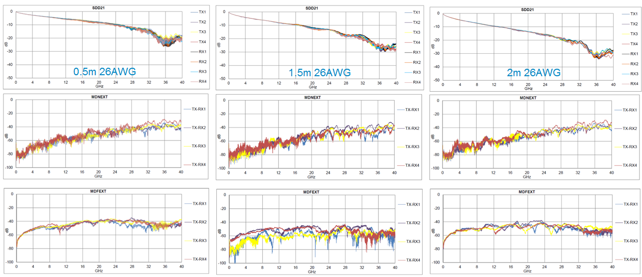
The passive channel model built as below is one of the typical scenarios, routed from the ASIC to the QSFP112 port which is a QSFP112 1x1 SMT belly to belly design through single PCB, and looped back via a 2m QSFP112 DAC for BER test.

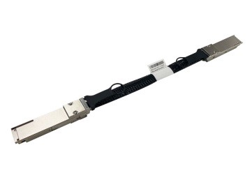
·Luxshare-Tech 26AWG QSFP112 DAC with 2m length
·Luxshare-Tech QSFP112 Connector with belly to belly mount
·Link Training Enabled
·180s Pre-FEC BER Result
The following BER test is a pre-FEC BER test based on the PRBS31 pattern and uses the diag tool under the chip SDK, the statistical duration is 180s. The insertion loss data of each lane in the loopback channel is based on the cascade of simulation modeling, and includes the elements from BGA ball to ball.
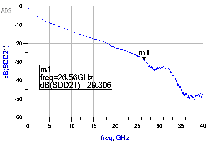
The pre-FEC BER reaches the e-5 to e-7 level when the whole test channel is close to the TP0~TP5 insertion loss specification defined in IEEE802.3ck 400GBase-CR4. After the 100% line speed traffic (post-FEC) test at room temperature for 60 hours, the results show that the port under test is error free, which corresponds to BER <1.4e-16 (95% confidence level).
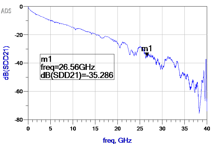
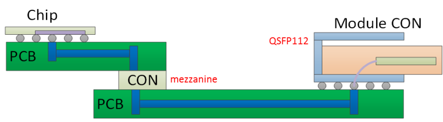
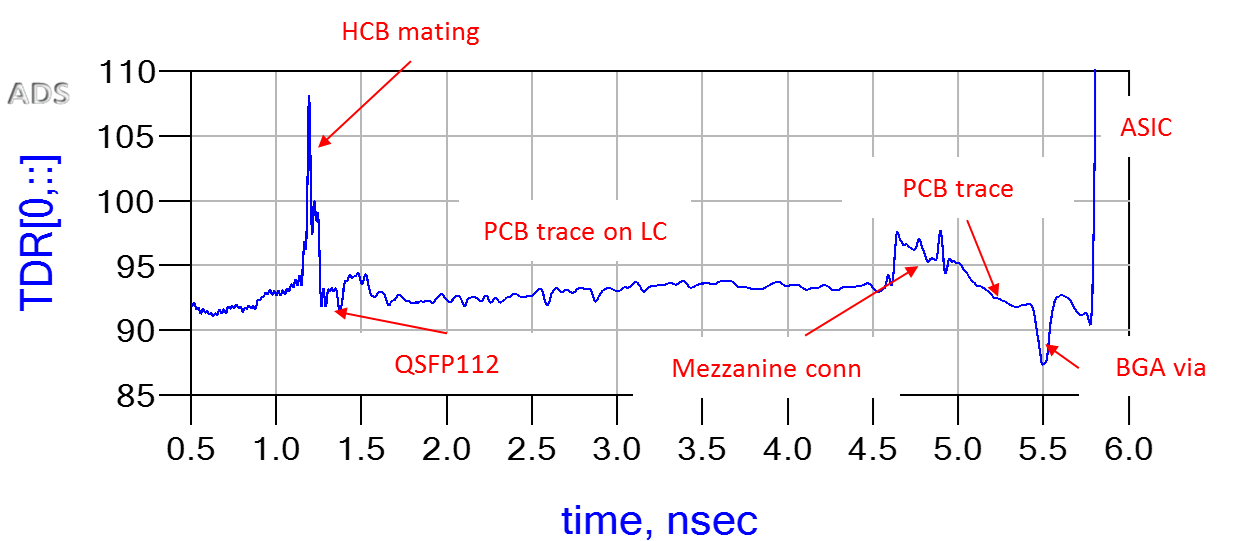
2.2 DAC loopback BER test of passive channel (across board-to-board connector)
This channel was built to verify the SI performance of a passive channel built across a board-to-board connector in a 112G-PAM4 electrical link.
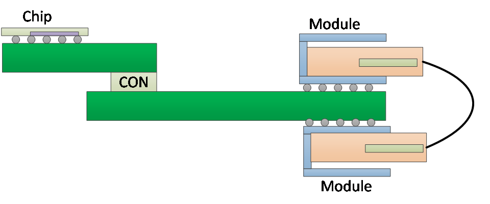
·Board to board connector(mezzanine)
·Luxshare-Tech 26AWG Cable with 1.5m length
·Luxshare-Tech QSFP112 Connector with belly to belly mount
·Link Training Enabled
·180s Pre-FEC BER Result
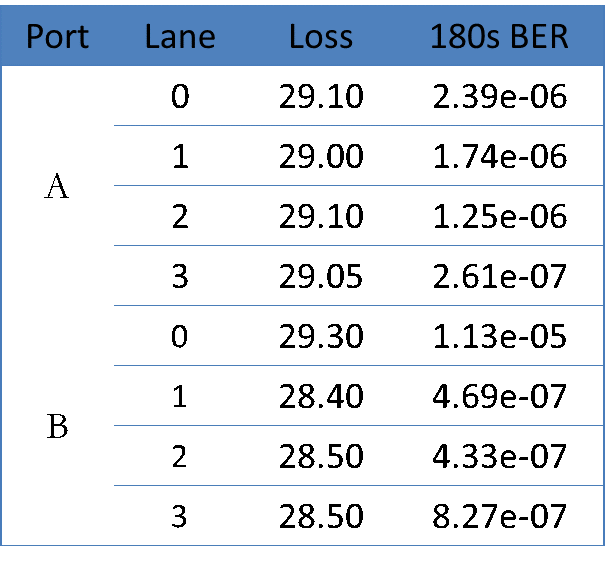
In this example, a channel with a loss far exceeding 400GBase-CR4 specification was intentionally built, and Pre-FEC BER under PRBS31 pattern reached the level of e-5 to e-6 at room temperature, and it showed error free after 100% line speed traffic (post-FEC) test at room temperature for 60 hours, which corresponded to BER <1.4e-16 (95% confidence level).
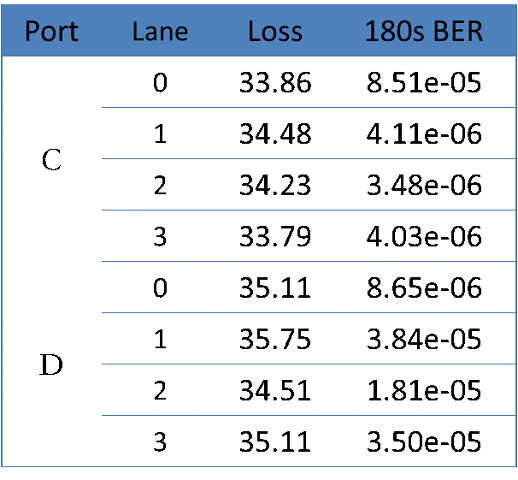
2.3 The test summary of electrical loop back channel
For the loss budget of the host channel, IEEE802.3ck allocates more loss budget to the C2M model than the CR model and more loss budget is given to the cable assembly, so many of the various host channels built in this prototype can only meet the C2M requirements but exceeds the CR specification in the DAC loopback model. We still carried out a long term test for these cases, and the statistics of 180s pre-FEC BER are shown in the figure below. All of these channels show error free after 100% line speed traffic test at room temperature for 60 hours.

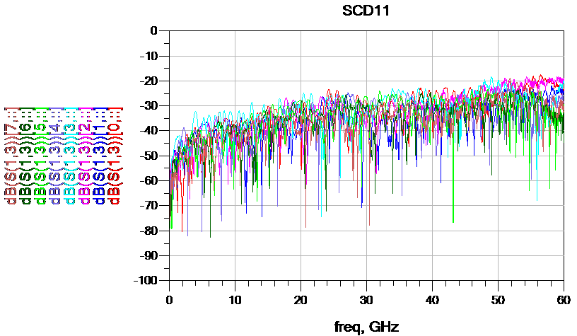
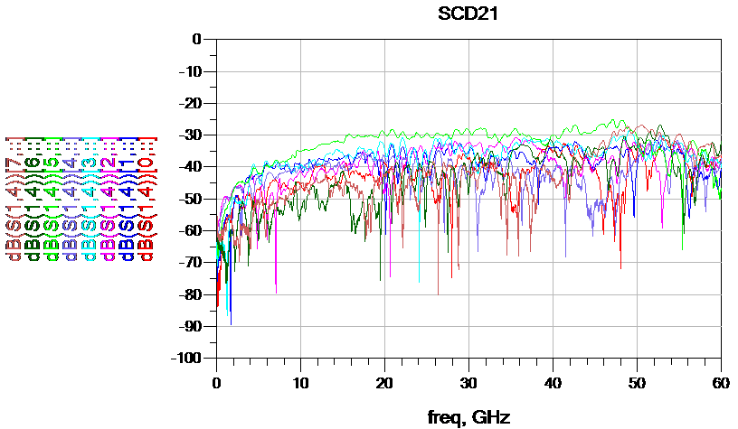
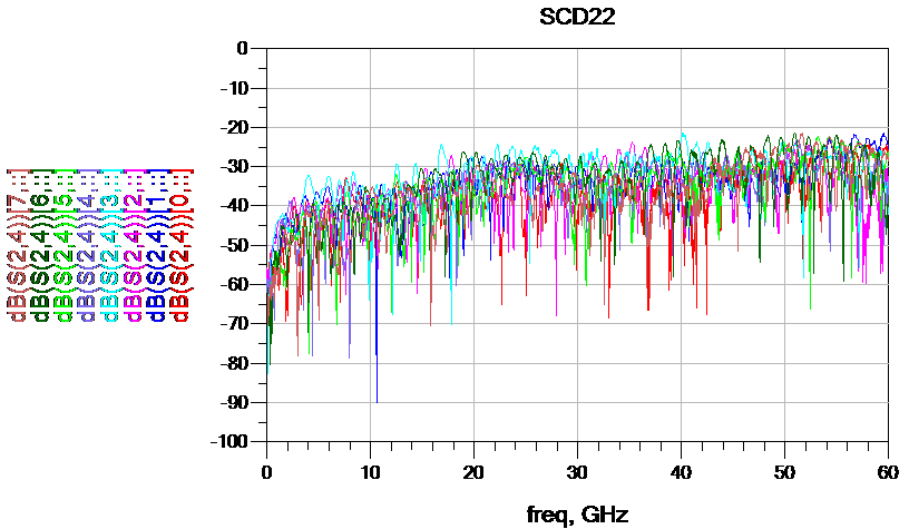
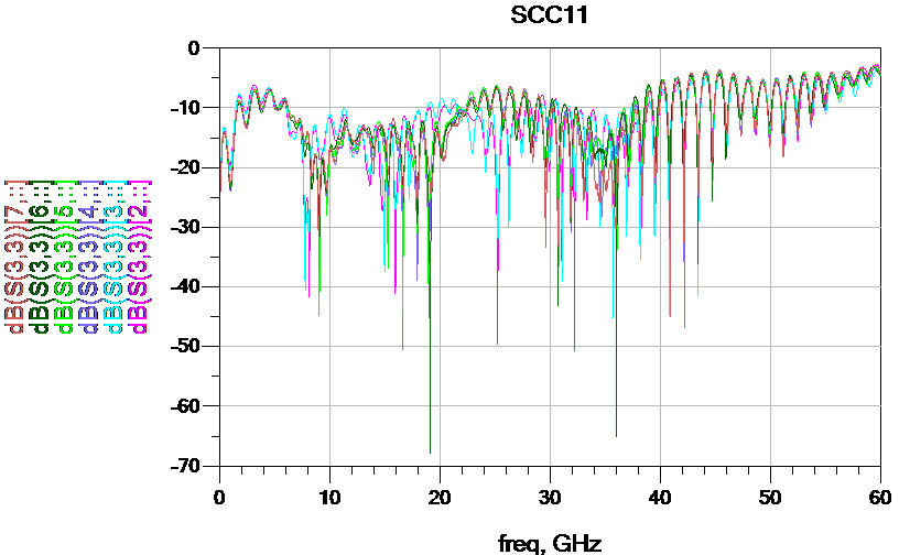
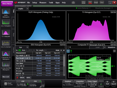
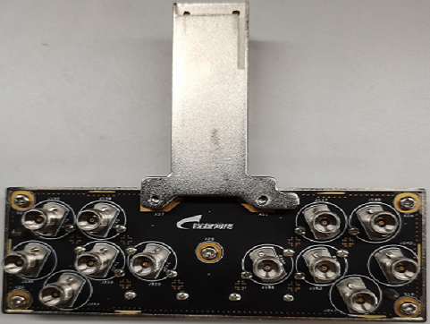
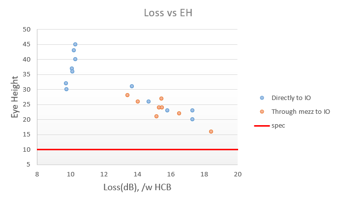
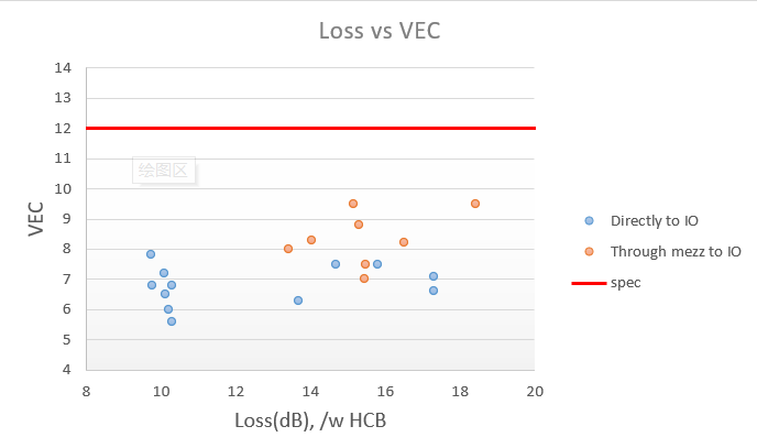
2.4 Host channel TP1a compliance test
In this prototype, various models of the passive C2M channel are built intentionally. There are complex channels such as routing from switch chip to the IO across the mezzanine connector, and simple channels such as routing from the switch chip to the IO through a single PCB directly. In accordance with the compliance point defined in IEEE802.3ck, all ports are tested for Host output TP1a and some of the results are shown below.
·Keysight N1000A+N1060A
·Pattern: QPRBS13
·Ruijie QSFP112 HCB
3.QSFP112 400G Optical Module Test
Up to now, some of QSFP112 MSA members have successfully delivered some preliminary engineering samples of different types of 400G optical modules. These samples have been tested end-to-end on a system-level prototype jointly developed by Alibaba and Ruijie. These module samples are contributed by Innolight, II-VI, Eoptolink and AOI, covering the types of QSFP112 400G-DR4, 400G-FR4 and QSFP-DD 800G-DR8 (2x400G-DR4).
The following BER data is the result of all these modules tested on all of the ports, generating the Pre-FEC BER statistics with a duration of 180 seconds. All tests are performed under normal temperature environment.
All of these links show error free after 100% line speed traffic test at room temperature for 24 hours, corresponding to a Post-FEC BER of lower than 3.5e-16 at 95% confidence level.
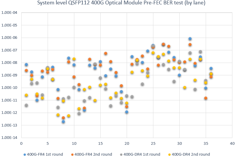
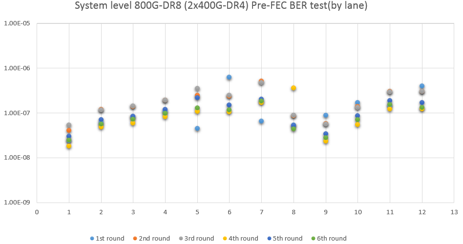
Please note that these data are only based on the test of preliminary engineering samples, not as any judgment or standard, but only shared for reference.
CAUTION CONCERNING FORWARD-LOOKING STATEMENTS
We are disclosing forward-looking information so that investors, potential investors, and other owners can better understand the mentioned Companies’ prospects and make informed investment decisions. The information in this press release contains “forward-looking statements” within the meaning of the Private Securities Litigation Reform Act of 1995. These statements can be identified by the fact that they do not relate strictly to historical or current facts. Any forward-looking statement made by the Companies speak only as of the date on which it is made. The Companies are under no obligation to, and expressly disclaim any obligation to, update or alter their forward-looking statements, whether because of new information, subsequent events or otherwise.